Wireless series
HUAWEI 3959-2100
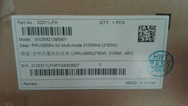
- Product description: HUAWEI 3959-2100
-
RRU3959/RRU3959w working in GSM mode and in the 900 MHz/1800 MHz frequency band
comply with the standard EN 301 502 V9.2.1. RRU3959/RRU3959w modules working in UMTS,
LTE or multi-standard radio (MSR) mode and in the 900 MHz/1800 MHz frequency band comply
with the standards ETSI EN 301 908 V5.2.1, 3GPP TS 37.104 and 3GPP TS 37.141.
For the RRU3959/RRU3959w working in GSM mode: When the S1 or S2 configuration is used and
the maximum output power is 60 W per carrier, the corresponding 60 W power license must be
obtained.
The output power is 1 dB less than the standard power when the RRU3959/RRU3959w is located at
a height of 3500 m to 4500 m; and is 2 dB less than the standard power when the
RRU3959/RRU3959w is located at a height of 4500 m to 6000 m.
Factors such as the inter-site distance, frequency reuse factor, power control algorithm, and traffic
model affect the gain achieved by dynamic power allocation. Therefore, in most cases, the network
planning can be based on the power specification achieved by dynamic power allocation.
In the power sharing mode, the power control and DTX functions must be enabled. In GBSS8.1, the
dynamic power sharing feature is mutually exclusive with the GBFD-113201 Concentric Cell,
GBFD-114501 Co-BCCH Cell, GBFD-118001 BCCH Dense Frequency Multiplexing, and
GBFD-117501 Enhanced Measurement Report (EMR) features. In GBSS9.0 and later versions, the
dynamic power sharing feature can be used together with these features. However, the dynamic
power sharing feature currently cannot be used together with the GBFD-117002 IBCA (Interference
Based Channel Allocation), GBFD-117001 Flex MAIO, GBFD-118701 RAN Sharing, and
GBFD-114001 Extended Cell features in GBSS8.1, GBSS9.0, and later versions.
Power sharing assumes a random distribution of UEs in the cell.
The output power per carrier in the output power tables indicates the maximum output power
supported by the network performance.
When two LTE carriers are configured, it is recommended that the power spectrum density (PSD) of
the two carriers be set to the same value. Power spectrum density = Carrier output power/Carrier
bandwidth (1.4 MHz and 3 MHz bandwidths are considered as 5 MHz bandwidth in this formula.)
For RRU3959w, the scenario where the third-order intermodulated signal falls in the receive
frequency range of a configured carrier is not supported.
Table 2-5, Table 2-6, and Table 2-7 show the typical output power for the RRU3959
supporting the 900 MHz frequency band and the following modes: GO, UO, and GU.
Table 2-5 and Table 2-8 show the typical output power for the RRU3959 supporting the 1800
MHz frequency band and the following modes: GO, LO, and GL.
Table 2-5 and Table 2-8 show the typical output power for the RRU3959 supporting the 2100
MHz frequency band and the following modes: UO, LO, and UL. Reference source not found. show the
typical output power for the RRU3959w supporting the 1800 MHz frequency band and the
following modes: GO, LO, and GL.
 ∷
∷